Section 6. Automatic Segmentation using Region Competition Snakes
This section gives step by step instructions on segmenting an image
using the region competition snake (in last section's terminology,
snake evolution that uses the region feature image). This section
assumes that you are working with the image MRIcrop-orig.gipl,
as recommended in Section
2, Step 1. We will segment the caudate nucleus and the ventricles
in this image. This section also assumes that you are using the label
file MRIcrop-seg.label.
You can, however, follow the general directions of this section
using a different image, but you will have to use your own judgement in
selecting various parameters.
Step 1. Discard the Previous Segmentation.
In Section 4,
we have created a manual segmentation. In order to perform the
segmentation automatically, we will discard the manual segmetnation.
This involves reloading the greyscale image.
 |
Select File | Load Data | Greyscale Image.
Use the History button to select the image
loaded most recently.
Step through the rest of the wizard, as descibed in Section 2.
|
Step 2. Select the Label to Use for Automatic Segmentation
We will be segmenting the caudate nucleus. We have to make sure that
the appropriate combination of the current drawing label and background
(draw over) label is selected.
 |
Make sure that the label "caudates" is
selected as the current drawing label
Make sure that "All Labels" is selected in
the Draw over drop-down box.
|

 |
The draw over label functions the same way
in automatic segmentation as in manual segmentation. It lets you apply
the results of automatic segmentation to all labels, to all visible
labels, to the clear label, or to a particular label. This gives you a
lot of creative control when segmenting multiple structures. For
instance, to segment a structure that is embedded inside another
structure, you can first segment the outer structure with label A
and then segment the inner structure with label B and
with the draw-over label set to A.
|
Step 3. Select the Region of Interest using the Snake Interaction
Mode.
The automatic segmentation component of SNAP requires a lot of
computer resources. Both the amount of memory and the time required to
compete a segmentation can be reduces by selecting a sub-region of the
image on which to perform segmentation. In this step, we will select a
subregion of the image that contains the caudate nucleus.
 |
Make sure that the slice is fully visible in each the slice
windows by pressing the Reset View buttons underneath
the slice windows.
|
 |
Select the snake tool in the IRIS toolbox (shown below)
|

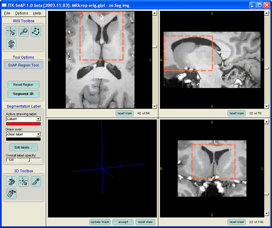
As you select the snake tool, a pink-colored dashed selection
box will appear at the border of the each slice in the slice
windows, as shown below:
The selection box displays the region of interest that will be used
in automatic segmentation. The use of word region here should
not be confused with region competition. The region of
interest is a rectalinear box, while the regions in region competition
are of arbitrary shape and are defined by uniform intensity. We will
now adjust the region of interest by dragging the sides of the
selection box
 |
In one of the slices position the mouse cursor near one of the
corners of the selection box
Hold down the left mouse button and drag
the mouse towards the center of the image. The size of
the box will be adjusted as you move the mouse.
|
As you are dragging the selection box, its edges change
color from red to yellow.
 |
Using all three slice windows, adjust the selection box to
include the left and right caudate nuclei. Try to simulate the
selection box in the picture below.
|
 |
If the selection box disappears in one of the slice windows,
that means that the crosshairs position is outside of the selection
box. You can adjust the crosshairs position in one of the adjacent
slices.
The crosshair position can be adjusted in this mode using the
left mouse button as usual. However, you will need to click a few
pixels away from the selection box to move the crosshairs.
|
Notice that the tool options control subpanel contains two buttons: Reset
Region and Segment 3D. The former is used to
reset the region of interest to the entire image. The second is used to
enter the automatic segmentaiton mode of SNAP.
 |
Once you have adjusted the region of interest, press the Segment
3D button.
|
Step 4. Familiarize Yourself with the Automatic
Segmentation Mode.
When you press the Segment 3D button,
the SnAP user interface changes considerably.
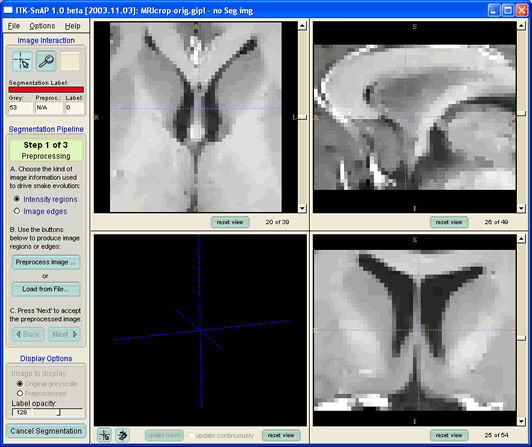
Let's look at some of the new elements that have
appeared:
- The slice windows have fewer buttons and only show the region of
interest selected in the previous step.
- The IRIS toolbar has been replaced by a smaller toolbar
containing only two buttons. These buttons are used to change the
crosshairs position and to zoom and pan around the region of interest.
The buttons are used in the same way as in the manual SNAP mode that
you are used to, except that fewer options for setting zoom are
provided.
- A large panel labeled "Segmentation Pipeline" appears underneath
the new toolbar. This panel contains the 'wizard ' used for controlling
automatic segmentation. We will work with this wizard extensively in
this section.
- A button labeled Cancel Segmentation appears at
the bottom of the control panel. You can use this button at any time to
return to abort the automatic segmentation and return to the manual
SNAP mode.
- A pair of buttons appear underneath the 3D window. These buttons
have the same functionality as the similar looking buttons in the 3D
toolbox in the manual mode.
 |
If the image slices appear washed out, i.e., have low
contrast, use the Intensity Curve window to change
the contrast as described in Section 3.
|
Step 4. Construct a Region Competition Feature Image.
Recall the concept of edge and region competition feature images
from the last section.In
this step we will construct a region competition feature image
appropriate for segmenting the caudate nuclei.
First let's tell SnAP which type of the feature image we will be
using:
 |
Select the option Intensity Regions in the
section A of the Segmentation Pipeline Wizard.
|
Now, let's estimate the range of intensities to which the voxels in
the caudate nucleus belong.
 |
Move the crosshairs around the caudate nuclei. Look at the
values of the grey level intensity, which is reported in a box labeled "Grey"
underneath the toolbar.
|
You will find that the intensities in the caudate range between the
high 40's and low 60's. This information is improtant for contructing
the feature image.
 |
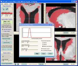
Press the button labeled Preprocess Image...
This button is used to construct the feature image. The following
window will appear
|
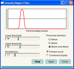
This window is used to specify the mapping between the greyscale
image intensities and the values of the feature image, which fall into
the range between -1 and 1.
 |
In the Intensity Region Filter window
- Set the threshold direction to Below and Above.
- Set the lower threshold to 48.
- Set the upper threshold to 63
- Set the smoothness to 1.7
|
 |
After you use the mouse to click on and move the knobs that
are used to change the threshold and smoothness values, you can use the
left and right arrow keys to move these knobs one value at a
time.
|
As soon as you change some of the parameters, the SnAP slice windows
will display the feature image instead of the grey image. As you change
the parameters, the slice windows are updated immideately. If you
uncheck the Preview result checkbox, the slice
windows will only reflect the values of the parameters when you press
the Apply button.
Our goal in setting the parameters is to make sure that the voxels
inside of fthe caudate nuclei are assigned positive values in the
feature image, and that the voxels outside of it are assigned negative
values. There are two ways to check that this happens:
 |
Move the crosshairs around in the slice windows (the
intensity region filter window will remain on top). Look at the values
of the feature image, which are reported in a box labeled "Preproc"
underneath the toolbar. |
or
 |
Check the Combined Display check box. The
greylevel image is shown again, but the pixels where the feature image
is positive are painted over with the color of the current segmentation
label, as shown below. This is an easy way to make sure that the pixels
in the caudate have a positive feature image value.
Uncheck Combined Display check box to see
the feature image again.
|
The smoothness value determines the steepness of the mapping curve.
It does not affect the sign of the feature function at any particular
voxel, but it does have an effect on the smoothness of the snake
evolution.
 |
When you are satisfied with the feature image, press Okay
to compute the feature image at all voxels and close the intensity
region filter window. |
 |
SnAP lets you save and load feature images. Just use the
appropriate menu items in the File menu. You can also
load feature images by pressing the Load from File... button
in the segmentation pipeline wizard.
|
 |
Voxels in feature images are saved as floating point numbers,
so some applications may not be able to load the saved images. You can
not save feature images in GIPL format because if does not support
floating point voxels. The Meta format is recommended.
|
We are now almost done with the first step of the Segmentation
Pipeline Wizard.
 |
Press the Next button in the Segmentation
Pipeline Wizard to proceed to the next step. |
Step 5. Initialize the Snake with Bubbles
The Segmentation Pipeline Wizard should be displaying "Step 2 od 3",
as shown below.
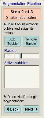
This step of the wizard is used to position spherical bubbles to
that initialize the snake, as described in the previous section.
 |
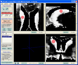
Move the crosshairs such that the crosshairs position is
inside of the right caudate nucleus in all three slice windows.
Press the Add Bubble button to place a
bubble at the crosshairs position.
Use the Radius slider to change the radius
of the bubble.
|
After adding a bubble, the SnAP window should look like this:
 |
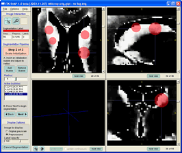
Place one more bubble inside the right caudate and place two
bubbles inside the left caudate.
|
The result should look something like this:
 |
To remove a bubble, select it in the list of bubbles
underneath the Radius slider and press the Remove
bubble button.
|
Finally,
 |
Press the Next button in the Segmentation
Pipeline Wizard to proceed to the next step. |
 |
As an alternative to using bubbles, you can use manual
segmentation to initialize the snake. Before starting automatic
segmentation, create a manual segmentation as described in Section 4 using the
same label that you wish to use for snake segmentation. The manual
segmentation will be used as the snake initialization, and you would
not have to add any bubbles.
|
Step 6. Run the Snake Evolution
The Segmentation Pipeline Wizard should be displaying "Step 3 od 3",
as shown below.

This wizard page allows you to set the parameters for snake
evolution, and it allows you to control the snake using VCR-style
controls.
 |
Press Set Parameters... to open the snake
parameter window.
|
The Snake Parameters window is shown below. This window consists of
two parts. On the left is a control panel used to specify various
parameters, mainly the weights of the propagation, curvature, and
advection forces that were discussed in Section 5.
These velocities are displayed using a fixed feature image, and not the
feature image that you are working with. Nevertheless, this image is
useful for understanding the relative contribution of the forces to
snake evolution
 |
The red curve for which the velocities are shown can be changed using the mouse. Left-click once in one of the four windows showing the curve and yellow 'control points' will appear. Move the control points by dragging using with the left mouse button. Try moving the curve and see how the foces change.
|
The snake parameter window also lets you save snake evolution
parameter settings to a file and to load them from a file.

 |
Change the curvature velocity weight to from 0.20
to 0.15
Press Accept to close the window
|
 |
The Mathematical Mode tab of the Snake
Parameters Window shows mathematical expression for the partial
differential equation that drives the snake evolution, and allows you
to set the parameters directly as constants in this equation.
You can also choose to display the experimental
equation, which contains more terms and gives you more control
over snake evolution.
|
 |
The Advanced Mode tab of the Snake
Parameters Window is discussed in the section on Tips and Tricks.
It can be used to speed up large segmentations.
|
Now that we've set the snake parameters, we are ready
to run the snake evolution. Notice the VCR-style controls located in
the Segmentation Pipeline Wizard.

These controls have the following functionality:
- The leftmost control is used to rewind the
snake after it had been evolving for some time.
- The second control is used to run the snake
until stopped.
- The third control is used to stop the running
snake
- The rightmost control is used to step the
snake, i.e., to run for a fixed number of iterations.
Underneath the VCR buttons is a control that allows you to set the
size of the step used in snake evolution. The larger the step value,
the fewer times will the user interface be updated as the snake
evolves. For small segmentations, it is advisable to leave the step
size at 1. Next to the step size dropbox is a display that shows the
current iteration.
 |
Press the Step button several times to run
the snake for a few iterations
Press the Run button once and watch the
snake fill up the caudates.
Press the Stop button when the caudates
have been filled up
Press the Rewind button if you want to
restart.
|
To see the segmentation result in 3D, you can press the Update
Mesh button underneath the 3D window, or you can select the Update
Continuously checkbox.
 |
Warning! Selecting Update Continuously will
degrade segmentation performace significantly, possibly by orders of
magnitude!
|
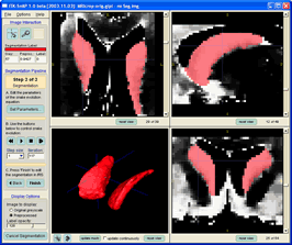
The result of the segmentation should look something like this.
Step 7. Finalize the Segmentation
The final step in the automatic segmentation process is to return to
the SNAP manual segmentation mode, incorporating the segmentation
results with other structures that have been previously segmented.
 |
Press the Finish button in the Segmentation
Pipeline Wizard
|
The Segmentation Pipeline Wizard will disappear, and the layout of
the SNAP control panel will return to normal.
 |
[Optional] Save your segmentation as
described in Section
4.
|
Step 8. Use the 3D Tools to Edit the Segmentation Results
In this step we will postprocess the results of the segmentation
using 3D tools.
 |
Press the Update Mesh button below the 3D
window to render the results
|
Now, let us examine the different tools available in
the 3D Toolbox, which is shown below.
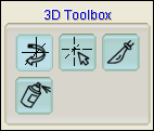
The toolbox contains four tools. Top to bottom, left to
right, they are
- 3D Trackball Tool: Used to rotate, zoom, and pan
in the 3D window.
- 3D Crosshair Tool: Used to set the crosshair
location by clicking on anatomical structures shown in the 3D window
- 3D Scalpel Tool: Used to repaint or erase parts
of the anatomical structures shown in the 3D window
- 3D Spray Paint Tool: Used to add anatomical
landmarks to the surface of anatomical structures shown in the 3D window
Let's begin by examining the 3D trackball tool:
 |
Select the 3D Trackball Tool
Press and hold the left mouse button and
move the mouse to rotate the 3D view.
Press and hold the right mouse button and
move the mouse up or down to zoom in and out in the 3D view
Press and hold the middle mouse button and
move the mouse to pan in the 3D view.
|
Now try the 3D crosshair tool:
 |
Select the 3D Crosshair Tool
Position the mouse over any point on the caudates and click
the left mouse button. The crosshair position will
move to the selected point and the slices shown in the slice windows
will be changed.
|
Now, something more complex. We will use the 3D scalpel tool to
assign different labels to the left and right caudate nuclei.
 |
Use the Edit Labels button to add two new
labels called 'left caudate' and 'right caudate' with different colors
(for information on editing labels, see Section 3).
|
 |
Select 'right caudate' as the current drawing label, and
select 'caudates' (the label used for automatic segmentation) as the
label to draw over, as shown below.
|

The 3D scalpel tool works by partitioning the space into two regions
separated by a plane. The segmentation labels on one side of the plane
are replaced by the current drawing label, as long as they agree with
the current setting of the draw over label. In order to use the scalpel
tool, we need to first rotate the 3D view such that a line can be drawn
between the two caudates.
 |
Use the 3D Trackball tool to rotate the 3D
view in such a way that the caudates can be separated by an imaginary
line, as shown below.
|
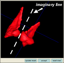
Now, we will use the 3D scalpel tool to actually draw a
line in place of the imaginary line
 |
Select the 3D Scalpel Tool
Click the left mouse button at one end of
the imaginary line separating the caudates
Move the mouse around the 3D window. You will see a white line
indicating where the 'cut' will be made, and an arrow indicating which
half of the space will be relabeled.
Click the left mouse button again at the
other end of the imaginary line
|
The result of this operation should look like this:

 |
If you are not satisfied with the 'cut', press the Reset
View button and try again.
|
 |
Otherwise, press the Accept button to
repaint one of the caudates with the active drawing label and press the
Update Mesh to see the result in 3D.
|
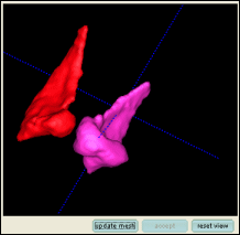
The 3D scalpel is a very powerful tool for editing
segmentation results. Using the clear label as the active drawing
label, you can erase parts of the segmentation that have leaked outside
of the caudates.
Step 9. [Optional] Segment the Ventricles
 |
Use the procedure outlined in the steps above to segment the
ventricles in the image. You will need to use the Above
threshold direction setting when creating the feature image.
|

The result should look like this

|
